Wednesday, 8 January 2025

An Adapter to Connect a Peak Design Clip Plate to the Sony RX10iv Camera. Photographic Adventures with a 3D-Printer. Part Two

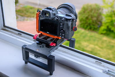
As I explained in Part One of this series, the Sony RX10iv has a serious design flaw in the strength and positioning of its tripod bush. I designed this 3D-printed plate to allow a Peak Design Clip Plate to be attached to the camera in a more suitable position while at the same time providing a greater degree of protection for the base of the camera.

As with the previous Arca-Swiss compatible tripod plate, this plate prevents movement which allows the screw to become loose and movement of the front end of the plate from the camera when the camera is tilted backwards.

When attached to the camera with the screw and either a strong elastic band or a cable tie around the lens barrel, the Peak Design Clip Plate—itself Arca-Swiss compatible—can then be mounted.

I have tried the device, using the Peak Design Clip as a ‘parking place’ when using the camera along with binoculars. I do not use the Clip for whether attached to a bag or a belt for carrying cameras on long walks but I have no reason to suppose anything would be amiss.

Other accessories could of course be substituted fot the Peak Design plate.

- - - - - - - - - - - - -

For those wishing to 3d-print their own adapter the relevant file is available together with a list of the metal hardware HERE.


- - - - - - - - - - - - -


Tuesday, 17 December 2024

A Tripod Plate to Correct a Design Flaw of the Sony RX10iv. Photographic Adventures with a 3D-Printer. Part One

The Sony RX10iv—or Mark 4 for those who can’t do Roman numerals—is an amazing camera in many ways and there is nothing else like it on the market. Although old in the tooth by modern standards and missing some features (it was released in September 2017) and recently discontinued it has a devoted following particularly with those using it for travel and wildlife photography. The maximum focal length of the zoom lens, equivalent to 600 mm in full-frame 35 mm terms, is a particular attraction.

I realised when I bought a Sony RX10iv camera that there was a problem with adding any sort of attachment, be it a quick-release tripod/monopod plate, a strap or a handle, to the tripod bush in the bottom plate. The tripod bush is so far back that any standard tripod plate sticks out under the screen to catch the unwary in the face when using the viewfinder. I quickly found that over the years since it launch, damage to the camera has been reported to the area of the camera behind the tripod bush and to the plastic base plate of the camera around the bush. There are photographs showing the destruction of the plastic plating  around the bottom edge of the camera caused by the use of a standard quick-release tripod plate.

The Tripod Bush is close to the rear edge of the
camera and a long way from the centre of gravity

Some of the damage seemed to have been cause by the screw holding the plate in place becoming loose and allowing the plate to rise at the front end and to press into and damage the back edge of the camera. A commercially available L-bracket seemed to offer a possible solution since rotational movement was very limited and  the screw remained tight for days of use. Using my small milling machine I also modified the plate to allow attachment of a Peak Design Clutch hand strap. I described that modification in a previous post.

In the early summer I decided to buy a 3D printer. Once I had learnt the necessary CAD in order to design things from scratch, I made Arca-Swiss compatible tripod plates that locked in place, at the rear by making a small lip that fitted up to the back of the camera without interfering with movement of the screen, and at the front by fitting under the lens barrel. Once screwed in place the tripod plate was rigidly fixed, allowed mounting on a tripod at onear the centre of gravity of the camera and was fitted with an anchor pocket for a Peak Design Clutch. I used that for days on end both on and off the tripod

Then another problem was pointed out to me. I had not used the camera at very high angles on the tripod. Pointing upwards there comes a point at which the centre of gravity is such that separation  of around 1 mm can be detected between the plate and the camera at the front end. That can only be explained by lack of rigidity of the tripod bush itself and flexing of the bottom surface of the camera. I found videos showing repairs being done to other parts of the camera and could not believe the tripod bush has such a flimsy means of attachment to the rest of the camera. The means by which the bush is attached seems inadequate for a camera of this weight and more suited to a small compact camera.

Several people have modified tripod plates and reported their designs on the two Facebook groups that cover the RX10iv. Some have lashed the plate to the camera around the tripod barrel with either strong elastic or an inflexible cable tie. One has a Mark I version of a cnc-produced plate in metal. Therefore, my final modification to the plate was to include that feature. Once a strong elastic band or a tight cable tie was fitted, there was no separation of plate and camera at any angle and nothing I could do to move the plate and thereby loosen the screw. A number of people have now bought and tried the latest—and final—version of the tripod plate and have found that it works as intended.


The 3D-printed tripod plate and its features


The final version, after many iterations and trials combines all the features I wanted into a single plate:

  • Arca-Swiss compatible with stops to prevent the plate from sliding off the mount
  • Allow smounting of the camera at or near the centre of gravity, very useful with all tripod/monopod heads but especially for pan-and-tilt video heads
  • A ¼ inch tripod bush in the plate allows other accessories to be attached
  • A pocket to accommodate a Peak Design Anchor enabling use of a Peak Design Clutch hand strap

I did of course wonder how strong tripod plates made of PLA plastic would stand up to normal use, and to additional forces that would not normally be encountered. In short I found it difficult to damage the plates with a hammer.

A considerable effort has been made by a number of people to overcome the problem of the RX10iv’s tripod bush—an effort that should not have been necessary had the designers not done such a bad job in the first place. 

…And over the past few months I have realised that the most useful accessory for a photographer is a 3D-printer.

- - - - - - - - - - - - -

HOW TO GET ONE

I have listed ready-to-use plates on eBay. Those interested should search for Arca-Swiss Compatible Tripod Plate Specifically for Sony RX10iv Mark 4 Camera in the eBay search window.

For those wishing to 3d-print their own plate the stl file, instructions and notes on other components required are HERE.


Peak Design Clutch Hand Strap shown attached to an earlier version of the
tripod plate

Friday, 7 June 2024

Fitting a Røde VideoMic Me-L or -C with Furry Windshield to an iPhone in a case - with the help of a bit of plastic card

Wind kills the audio of video recorded in the field. Fitting most microphones plus windshield quickly to a phone in a case is a pain. Some sort of clamp with a cold shoe mount is needed together with wires to reach the Lightning, or USB-C socket. Three leads/adapters may be needed to get from the microphone to the socket (e.g. TRS-TRS, TRS to TRRS and TRRS to Lightning). In a simple set up these leads get in the way of the hands. The type of microphone that overcomes these problems is one that plugs directly into the Lightning socket or the USB-C socket on the latest iPhones. However, there is a snag. Major manufacturers like Røde have made the stem from the body to the plug such that it fits an iPhone without a case but not when a cases from most manufacturers is fitted; the stem is simply too short. Since, when on the move, a protective case seems the norm, the Røde VideoMic Me-L (Lightning) or Røde VideoMic Me-C seems out of the question. However, there is a way to plug the microphone directly into phone. That is by using a docking extender. The ones I bought (they come in packs of two) are shown as suitable for attaching the Shure MV88 microphone to an iPhone within a case. Similar extenders are available for USB-C sockets. A slide-on clip is supplied with the microphone and I have this pushed on to make contact with the docking extender. Whether that helps stabilise the linkage I do not know but it may help a little.

I was pleased with the firm push-in attachment the VideoMic Me-L made with the extender and the extender with my iPhone 14 Pro. There was however one irritation. The occasion I use this microphone is in wind, i.e. with the furry windshield, a.k.a ‘dead cat’ or in this small version ‘dead kitten’. But inserting microphone+extender with the windshield already in place was tricky because the long hairs could easily get dragged between the contacts of plug and socket. To overcome this I glued (cyanoacrylate ‘superglue’) a small strip of styrene plastic (approximately 0.8 mm thick) to the docking extender. That keeps the fur out of the way when the microphone is plugged in. The styrene strip slides over the edge of the phone case.

I have tried the docking extender in a number of different i-Phone cases and it works with them all.


The complete set-up. The iPhone is in a Peak Design Mobile Everyday case
with Mobile Tripod attached


With modified docking extender


The docking extenders (pack of 2) I bought for my iPhone 14 Pro are on Amazon as:

i-Phone Docking Extender Adapter Converter. i-Phone Extension Adapter Connector… The pack is labelled Male i-OS to Female i-OS

Similar extenders are also available for phones with USB-C sockets, e.g. iPhone 15 and Røde VideoMic Me-C


Sunday, 26 May 2024

Sony RX10iv. Coping with the Tripod Bush — Modifying an L-Bracket Plate to fit a Peak Design Clutch Hand Strap

The Sony RX10 Mark IV is an amazing camera in many ways and there is nothing else like it on the market. Although old in the tooth by modern standards (it was released in September 2017) and there seems no sign that a new model offering the same functionality will ever be made, it has a devoted following particularly with those using it for travel, wildlife still and video photography.

It does, like all camera designs, come with its own problems. One of the most annoying is the position of the tripod bush, near the back edge of the body. Fitting a quick-release tripod plate or any other attachment presents two problems. The first is that the plate protrudes from the back of the camera. The second is that if any attachment becomes loose it can rock in the bush and damage the edge of the body. There are photographs online showing the damage that has been done by a tripod plate or one of the types of strap that screws into the bush. I can only think the designers, trying to accommodate the large zoom lens (equivalent to 24-600 mm in 35 mm terms with a maximum aperture of f/2.4) could only find one place to put it.

There is a similar problem when trying to fit a Peak Design Clutch hand strap. I prefer a clutch, particularly for holding this type of still-video hybrid cameras and for using it and a small bag over the shoulder when using binoculars. The PD Clutch uses a small Arca-Swiss style plate to which the Anchor Link for the strap is attached. I realised that a bottom plate or L-bracket that screwed into the bush but which provided another bush near the centre of the body would be essential. I found one on Amazon UK. It is listed as Aumi L Plate Bracket QR Hand Grip Holder for Sony RX10. The plate is Arca-Swiss compatible, making tripod mounting a simple matter. However it lacked anywhere I could attach the PD Clutch. I would have to had added the small PD plate in addition to the Aumi Plate Bracket, making the camera even taller. Therefore, I decided to modify the Aumi Plate Bracket in order that a PD Anchor Link and hence a Clutch strap could be fitted.

Modifying the Aumi plate is not as simple as just drilling a hole for the Anchor Link. Material must be removed from the top and bottom of the plate in order for the PD Anchor Link to lie flat. In addition, the remaining bar cannot be too wide or too tall otherwise the Anchor Link will not fit. After working out the dimensions I used my small milling machine (Proxxon MF70) to make the cuts in the aluminium.

The diagrams show the dimensions for milling. At this stage I made no further modifications but on fitting the clutch I find the camera would not stand flat because the plastic fastener at the end of the strap came to lie below the plate. Since the part of the plate that went around the battery compartment seemed superfluous (and got in the way slightly when changing battery) I then removed it, taking care to leave sufficient of the lip that extends upwards to prevent the plate from rotating once the bolt is tightened. After that the camera lies flat on a surface. When all that was done I sprayed the bare parts with black paint and fitted the Clutch strap.

The first real test was a week’s trip to Portugal. I was prepared (a wrench of the right sizes in the pocket) should the bolt holding the bracket have come lose but it was as tight after a week of constant use as after I first put it in.

Therefore, I could use the Clutch strap and put the camera on a tripod or monopod with an Arca-Swiss style head without adding or changing anything. By adding another Anchor Link to the Clutch or to the adjacent strap lugs I could even add my PD neck strap. The tripod bush on the plate can also be used for accessories like a pistol grip.

I wish at times I had a 3D printer. I can envisage a very neat and light plate design.


The completed job with modified L-bracket plate and Peak Design Clutch Strap attached


Unmodified plate showing where the attachment for the Peak Design Anchor Link was made


Bottom and top views of the plate after the attachment point was made but before the loop
around the battery cover was removed


Top (camera side) view of the modified plate
I left sufficient of the bar at bottom right for the camera-facing lip to prevent rotation of the plate


Wednesday, 15 May 2024

Canon Legria HF G70 Camcorder for Wildlife? NO. Repeat NO

 I gave my first impressions of the Canon Legria (Vixia in the US) HF G70 Camcorder in February 2023. I concentrated on image quality, noise with the small sensor and focusing. All I found to be very good. However, I realised on my first big trip with this camcorder that there were two serious flaws which made it completely unsuitable as a camera for filming wildlife. So serious did they turn out to be that I got rid of the camera—with curses sending it on its way.

Problem 1. Start-up Time

Having already decided I did not like the flimsy switch used to turn the camera on, I realised that it took an inordinate length of time for the camera to actually turn on and permit the record button to be pressed or to zoom the lens. A start-up screen even appeared saying nothing of any importance, reminiscent of those we had with mini-DV tape camcorders in the past. Out came the stopwatch: 8½ seconds. Enough time for bird to appear, bow three times and disappear over the horizon. By contrast my Nikon Z7 was timed at under 1½ seconds and my Sony RX10iv took under 4 seconds to turn on and to zoom to its longest focal length. I just wonder whether some old firmware Canon installed in camcorders in the past is still being used, leaving time for tape or hard drives to start-up.

Problem 2. Hand-held at long focal lengths

As I was zoomed into more distant animals I noticed a strange shimmer towards both sides of the image. I had read in the manual that at long focal lengths with DynamicIS (stabilisation) turned on ‘the edges of the picture may be adversely affected (ghosting, artifacts and/or dark areas may appear) when compensating for a high degree of camcorder shake)’. Had I accidentally left it on DynamicIS? No. It was happening with StandardIS. It was clearly an image stabilisation problem. With IS off the artifacts disappeared but then of course the image bounced around all over the place. Was it just me, not holding the thing still enough? To test that I asked people with much steadier hands than me to try it: the artifacts were still appearing. To cut a long story short, after much testing on my part at different focal lengths, the camcorder went back to Canon with sample video. They returned it saying there was nothing wrong!

Well, nothing wrong if you stick to wide-angle shots handheld and nothing wrong if you have it on a tripod. But lots wrong for handheld wildlife or even subjects like sports.

I concluded as it went out of the door that this was yet another camera designed for the convenience of the designer rather than the real needs of the people buying it. Something surely must have gone wrong with the design of the stabilisation system compared with other brands. Not only did Canon launch a camcorder with incorrect marketing information (that it has infrared capability), as I reported previously, but one that performed so miserably, both technically and ergonomically, in the field.


…The first thing I checked on the Sony RX10iv when it arrived was handheld video at 600 mm equivalent focal length on the optical zoom. Was there a problem à la Canon? No.

Thursday, 14 December 2023

SONY RX10iv. Making Soft Release Buttons That Fit and Stay in Place

I bought the Sony RX10iv mainly as a video camera. I assigned video on/off to the main shutter release button (the Movie button is small and awkwardly positioned as on so many cameras mainly designed for still photography) for use when in dedicated video mode. I was delighted to find the shutter button has an old-fashioned screw-in cable release socket. It would therefore take a standard screw-in Soft-Release Button. I thought that would be a useful accessory since the shutter release is fairly small and only just projects above its surrounding ring. For starting video recording on or off a tripod, especially in cold conditions, a larger, raised button would surely be better.

The Soft Release Button was named not because it is made of soft material (although some were made partly of hard rubber) but because it was thought it helped photographers squeeze the shutter release and therefore avoid camera shake. It was a standard if little used accessory in the days of film cameras.

I soon found there were oodles of soft release buttons on Amazon and eBay. What could possibly go wrong? In short, although the several I tried screwed into the socket, they did not stay there. The slightest movement, even turning the camera upside down, resulted in the button falling out. They were soon sent back for a refund. Could I make my own?


My home-made Soft Release Button

Accessories that fit into the cable release sockets are supposed to be interchangeable. They once weren’t—Leica had its own. The specifications of ‘Shutter cable release tip and socket’ are described in ISO 6053 with two variants, tapered threads and parallel threads. The RX10iv socket has a tapered thread and so did the buttons I bought from Amazon that did not stay in place.


Standard cable release tip I have had since the 1960s

I had some 3 mm grub screws, with parallel threads ending in an unthreaded cone, in the garage. I found that they fitted and tightened perfectly. It was then a case of finding some way of attaching a button to make my own soft release.

I made three different versions. The only points of design I had to bear in mind were not to make the diameter of the button so wide as to foul the surround of the socket (I set a maximum of 11 mm) and not to set the button so low that it might hit the socket surround before firing the shutter. All the items I used are easily available from Amazon and/or eBay and use common tools, except for my final design which needs a lathe.

I also discovered that soft release buttons decorate cameras as more of a fashion statement than utility demands. Luxury versions made of wood or stone and bearing decorations are available at high prices. It is amazing what people will pay for. For those seeking a functional version that works on a real working camera, an outline of my three versions is shown in the accompanying diagram. The following notes provide further explanation of what is needed.


Style 1. Very simple construction

This is the simplest to make. The only problem that might eventually arise with it in use is if the button were to receive a hard knock, sufficient to dislodge the epoxy used to attach it to the metal parts.

1 M3 6 mm cone point grub screw

1 M3 Nut

1 Button  - sewing box raided - measured at 10 x 2.2 mm; 2 hole

Loctite threadlocker

Epoxy (Araldite Rapid Steel - I had opened tubes already)

Milliput Extra Fine filler

Spray paint

Threadlocker was applied to the blunt end of the grub screw which was screwed into the nut until the ends were level. Excess Loctite wiped off and left overnight. Button attached with Araldite and left overnight. Holes and depression in button filled with Milliput, smoothed and left overnight. Top sanded flat and spray painted (threads protected by pushing into cardboard).


Style 1 Components

Style 1 on camera

Style 2 Taller and more robust

1 M3 10 mm cone point grub screw

2 M3 Nut

1 M3 8 mm diameter washer

Loctite threadlocker

Epoxy (Araldite Rapid Steel - I had opened tubes already)

Milliput Extra Fine filler

Spray paint

1.5 mm Styrene Sheet (as sold for model making)

11 mm disc punched out of styrene sheet (cheap hollow punch sets for leather etc on Amazon). One solid hit (against a solid piece of timber) with a heavy hammer produces a clean circle. Centre drilled 3 mm. Edges cleaned up with sandpaper.

Threadlocker was applied to the blunt end of the grub screw. Two nuts added leaving room for the washer and half the thickness of the styrene disc. Excess Loctite wiped off and left overnight. Washer and styrene disc attached with Araldite and left overnight. Hole in disc filled with Milliput, smoothed and left overnight. Top sanded flat and spray painted (threads protected by pushing into cardboard).


Style 2 components

Style 2 on camera

Style 3 Lathe needed

Brass button 11 x 3.3 mm turned on lathe. Centre drilled 2.5 mm. Tapped 3 mm

1 M3 6 mm cone point grub screw

Loctite threadlocker

Milliput Extra Fine filler

Spray paint

Threadlocker was applied to the blunt end of the grub screw. Inserted into brass button, leaving 3.5 mm protruding. Excess Loctite wiped off and left overnight. Hole in brass filled with Milliput, smoothed and left overnight. Top sanded flat and spray painted (threads protected by pushing into cardboard).


Style 3 on camera


And yes they do work as intended—and stay in place.

I have since read that other owners of cameras with cable-release sockets have experienced similar problems with the commonly available commercial soft release buttons. Some have resorted to using threadlocker in the socket (not recommended since heat needed to remove it) or nail varnish. Better to just make your own.


Tuesday, 21 February 2023

CANON LEGRIA HF G70 CAMCORDER Review 2. Noise? What Noise? The swings and roundabout of sensor sizes and lens apertures


It is a truism that a large sensor will show less obvious noise in low light than a small sensor. Given equal processing and noise reduction algorithms, a camera with a large sensor and not too densely packed pixels must perform better in low light than a camera with a tiny sensor. That sounds obvious but in practice there is another factor at play in video recording: the lens aperture. Since the exposure for video is constant or virtually so (i.e. 1/50th of a second for 25 frames per second or 1/60th for 30 fps) the aperture of the lens is the determinant of how much light reaches the sensor over that period. More light equals a higher signal:noise ratio and, therefore, less noise. Some people, many online, interpret having to increase the ISO setting, or gain, as the cause of the noise. That is not so. Increasing the ISO setting simple increases the gain of the amplifier to make the image visible; both signal and noise are increased.

The Canon HF G70 has a 1/2.3”* sensor. The maximum aperture varies across the zoom range between f/1.8 and f/2.8. To see how good—or bad—the noise was in low light I compared it first with the main camera on the iPhone 14 Pro (‘main’  f/1.78, said to be size 1/ 1.28"). This test was done in a dim, northerly facing room in daylight. The Exposure Value was 4. In the deepest shadow area there was a little noise and I could not find any difference between the Canon HF G70 and the iPhone. I then compared the HF G70 with my Nikon Z7, which because of the very large number of pixels is known to be noisier than the Z6. I put on a 50mm f/1.8 lens. The Exposure Value was 4.3. Again there was a little noise at f/1.8 (ISO was 800), slightly less perhaps than on the HF G70 and iPhone. However, when I turned the aperture to f/4 (keeping the shutter speed at 1/50 and letting the ISO setting increase to 4000), there was marked noise. In other words, my Nikon Z7 in full-frame mode at f/4 was noisier than the Canon HF G70 and the iPhone 14 Pro at f/1.8. The difference between f/1.8 and f/4 is 1⅓ stops (EVs) but of course a more than doubling of the light hitting the sensor.

In other words we are talking about trade-offs with apertures, sensor size and depth-of-field. One advantage of using a full-frame camera is being able to isolate a subject in a narrow depth-of-field. However, with video, the depth-of-field at f/1.8 is wafer thin. With a 50 mm lens at a distance of 5 metres it is only around 20 cm. Therefore, it is highly likely that I would want to use a smaller aperture. With a smaller sensor, the same depth-of-field can be attained at a larger aperture so what you gain on the swings by using a camera with a larger sensor, in terms of noise, can easily be lost on the roundabouts of using a smaller aperture.

This is all a very long-winded way of saying that I am very pleased with the performance of the Canon HF G70 in low light. My guess is that Canon have got it as good as it can be with the current state of technology. All my trials have been with 4k video. I note that Canon in their marketing of this camera stress ‘Over Sampling HD Processing High quality Full HD. Uses the 4K UHD sensor to deliver superior Full HD images’. I haven’t tested that yet.

While I was doing all this I realised something I had not fully taken in before. When my Sony AX-53 (also a 1/2.3” sensor) broke down in use (cash refunded by Amazon) and I unwisely bought the Sony AX-700 just before covid lockdown (camera also broke down in use and just out of extended warranty but with very few minutes on the clock) that the advantages of the larger (the so-called 1” sensor) in terms of noise and of a slight isolation of any subject at larger apertures, were offset at least partially, by the smaller maximum aperture of the lens. The AX-53 is f/2-f/3.8 over its zoom range; the AX-700 f/2.8-f/4.5. The Canon HF G70 as I noted earlier is f/1.8 and f/2.8 (over a much wider zoom range).

Unfortunately, it is not worth trying to show the videos of the trials; the definition here and on YouTube is just not good enough for any difference to be illustrated. It is also worth pointing out that while I always try to take 4K, I normally put this on a 1080 timeline thus giving me the opportunity to zoom in by cropping without losing definition. I did that with all the samples (where I could spot the noise on playback on my 24” Mac with 4K Retina Display). However, when I did as I usually do, output the video as an MP4 file and looked at it on a television (no, not one of those huge things that fill a wall) I could see no noise, except for the slightest flicker evident in the footage from the Z7 at f/4.

*Desperately needed is some international standard for sensor sizes in cameras. The use of fractions of inches and the like can be utterly confusing. We need  the dimensions in mm--a simple statement some manufacturers are very reluctant to state. That, together with the number of pixels should be a standard imposed. 

Coming Next: Ergonomics and Setup